Technical Library

Electrostatic Discharge Prevention
July 13, 2021
Electrostatic discharge is a potentially large problem for those working with fragile electronics. If not properly accounted for, it can cause expensive amounts of damage. Luckily, there are steps that can be taken to completely reduce the risks brought on by static electricity. By following the guidelines in this app note, a safe work environment can be created for productive electrical research and development.
Automatic Fixture Removal Operating Manual
July 8, 2021
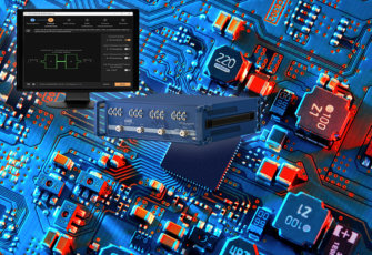
Automatic Fixture Removal’s new SW release addresses de-embedding with comprehensive methods, tailored to specific fixture properties. It moves the calibration plane toward hard-to-access components and guides the de-embedding process. Thru, reflect and up to four-port single-ended fixtures are supported. AFR SW supports all CMT 2-port Compact VNAs to 44 GHz and 2- and 4-port Cobalt VNAs to 20 GHz.
10 Things You Didn’t Know Your CMT VNA Could Do
June 4, 2021
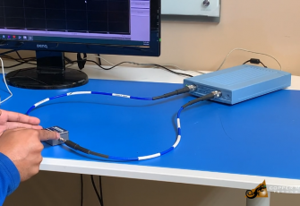
A VNA is a powerful tool capable of doing various calculations and operations. We hope you can learn something about the CMT VNAs with the information shared.
Third Order Intercept
October 30, 2020
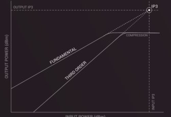
Third order intercept or IP3 plays a significant role in device characterization and verifying RF performance. With the use of a Copper Mountain Technologies VNA and the free and easy-to-use IP3 software plug-in, third order intercept can be easily measured without the need for a complex setup.
Power Calibration with Copper Mountain Technologies VNAs – Quick Start Guide
September 1, 2020
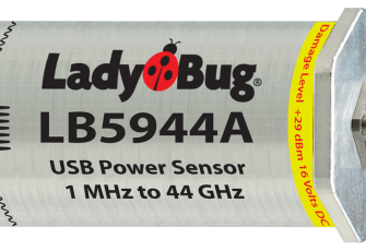
Performing amplifier, mixer, or other sensitive DUT measurements accurately and correctly depends on proper setup and appropriate calibration. Power calibration using power sensors at the DUT calibration plane ensures precise results.
Automatic Fixture Removal Plug-in Method Selection
August 5, 2020
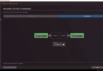
Automatic Fixture Removal (AFR) plug-in serves to simplify a device under test (DUT) measurement process based on a Vector Network Analyzer (VNA) when direct access to DUT is not possible. A principal challenge in these cases is correct elimination of fixture effects.
Dual Band Measurements with a 4-Port VNA
June 24, 2020
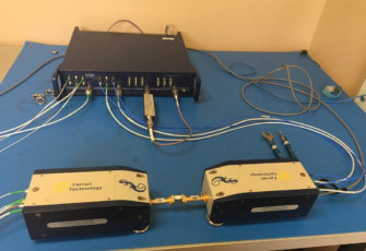
The dual band measurement setup is ideal If you have a 4-port frequency extension compatible VNA and are working in an application that deals with multiple frequency ranges. For example, some 5G applications deal in a low frequency band (below 6 GHz) as well as the mmWave frequency band.
Determining Resonator Q Factor from Return Loss Measurement Alone
June 23, 2020
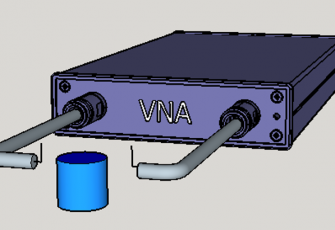
It is not uncommon to want to measure the Q factor of a resonator. This might be to determine its suitability for use in a coupled resonator filter or to evaluate the performance of an RFID tag. Generally, this measurement is made with very light input and output coupling to reduce the loading effect of the 50 ohm source and load impedances. Coupling to and from the resonator might be done with two electrically short antennas or loops to couple to the electric or magnetic fields of the resonator.
Introduction to RNVNA, A Multiport Network Analysis Solution
May 1, 2020
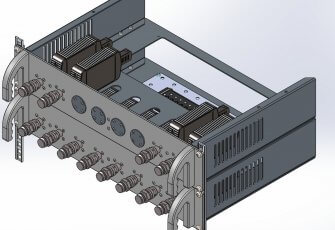
In many applications it is necessary to make multiport measurements. The RNVNA is capable of performing these up to 16 ports. Each of the 16 ports will make individual vector reflection measurements and scalar measurements from port to port. In other words, S11, S22, S33 and so on will be complex measurements and S21, S31, S41 and so on will be scalar only measurements.
Vector Mixer Measurements
April 13, 2020
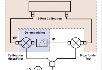
The vector mixer calibration method allows for measurement of mixer transmission complex S-parameters including phase and group delay of the transmission coefficient. The vector mixer calibration method ensures a matching frequency at both test ports of the analyzer, in normal operation mode. The vector mixer calibration procedure will be outlined in this app note.

Signal Integrity Tips and VNA Measurements eBook from Microwave Journal
January 15, 2020
Signal integrity addresses the losses and types of signal degradation that can happen along the signal path (channel) between a transmitter and a receiver. Signal integrity is becoming more and more important as digital signal speeds and analog frequencies are rapidly increasing making circuits much more sensitive to any losses or variations in the path. This eBook provides information and instruction on making accurate signal integrity measurements with emphasis on the VNA as a tool.
Time Domain Analysis with a CMT VNA
October 2, 2019
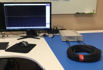
A Vector Network Analyzer (VNA) natively measures complex S-parameters of a device under test (DUT) in the frequency domain mode by sweeping across various frequency points. While there is an exhaustive list of measurements that can be accomplished in the standard frequency domain mode – using the advanced inverse Chirp z-transformation, the measurements can also be simultaneously analyzed in the time domain mode. This gives the added advantage where the two fundamental modes of analysis can be performed by one single instrument.
Using a VNA for Power Plane Impedance Analysis
September 10, 2019
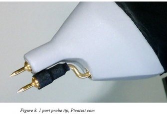
Senior RF Design Engineer Brian Walker at Copper Mountain Technologies was published on Signal Integrity Journal for his article on using a VNA to perform power plane impedance analysis. He writes, "A vector network analyzer (VNA) is an essential measurement tool for RF design and is often used to characterize the performance properties of filters, amplifiers, antennas, and the like. It might be surprising to learn that this versatile tool may also be used to measure and optimize the power supply systems which drive digital, analog, or RF circuits."

IEEE Paper: One-Port Vector Network Analyzer Characterization of Soil Dielectric Spectrum
August 13, 2019
Using USB VNAs with Single Board Computers
July 12, 2019
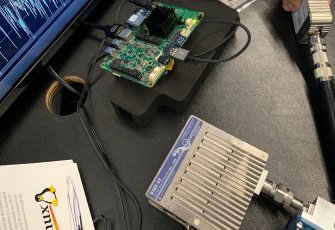
Copper Mountain Technologies provides VNAs without a built-in computer, which enables them to be highly compact, lightweight, and operate on very low power. These characteristics allow the VNAs to interface with single board computers to work in situations with strict space limitations, and to be integrated in battery-powered systems. This App Note introduces how to set up single board computers to work with CMT USB VNAs.

TRL Calibration
July 8, 2019
Thru-Reflect-Line (TRL) calibration has a number of advantages over the Short-Open-Load-Thru (SOLT) method often used in VNA calibration. Read the app note to learn more about the TRL calibration method.
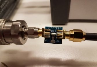
Make Accurate Impedance Measurements Using a VNA
June 21, 2019
Three different methods can be applied to accurately measure passive components with a vector network analyzer. A vector network analyzer (VNA) is a very useful test instrument for characterizing RF circuits and amplifiers. But what about measurements of simple passive components? What’s the best way to characterize a chip capacitor or an inductor—or even a resistor? Senior RF Design Engineer Brian Walker at Copper Mountain Technologies wrote an article for Microwaves & RF discussing how to make accurate impedance measurements using a VNA.

Design Trends in Automotive Electronics and Radar Sensors eBook from Microwave Journal
June 17, 2019
Automotive electronics is experiencing a big boost from the trends toward more connectivity, autonomy and electrification. These trends started years ago with the addition of satellite radio and GPS but is quickly increasing with cellular connectivity, ADAS and autonomy being incorporated into more vehicles. Yole Development predicts a 23% CAGR from 2016-2022 for mmWave radar sensors growing to $7.5 B at the module level. The global automotive electronics market is predicted to grow from its current value of $270B to more than $400B by 2024 according to Global Market Insights, Inc. The development of intelligent vehicle technologies owing to the need for advanced safety and comfort parameters will drive the market growth according to the company.
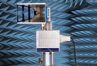
Precision Antenna Measurement Guide eBook from Microwave Journal
June 17, 2019
Antenna measurements are difficult to make due to their multi-directional nature, their cables/connections to equipment and interfering signals in the environment. The measurement setup, surrounding environment and physical connections all need to be carefully specified and setup, paying close attention to the instruments and materials used.
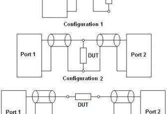
Measurement of Electronic Component Impedance Using A Vector Network Analyzer
March 26, 2019
Electrical impedance is an important parameter used to describe individual electrical circuit components or a circuit as a whole. Impedance is a complex number, in which the real part is represented by resistance and the imaginary part is represented by reactance. Once the impedance is determined, one can calculate other parameters such as resistance, inductance, capacitance, scattering coefficient, and figure of merit; draw an equivalent circuit of the measured circuit and predict its behavior over the desired frequency band.
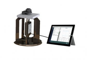
A New Dielectric Analyzer for Rapid Measurement of Microwave Substrates up to 6 GHz
November 26, 2018
This paper presents a new measurement method based on the parallel plate capacitor concept, which determines complex permittivity of dielectric sheets and films with thicknesses up to about 3 mm. Unlike the conventional devices, this new method uses a greatly simplified calibration procedure and is capable of measuring at frequencies from 10 MHz to 2 GHz, and in some cases up to 6 GHz. It solves the parasitic impedance limitations in conventional capacitor methods by explicitly modeling the fixture with a full-wave computational electromagnetic code. Specifically, a finite difference time domain (FDTD) code was used to not only design the fixture, but to create a database-based inversion algorithm. The inversion algorithm converts measured fixture reflection (S11) into dielectric properties of the specimen under test. This paper provides details of the fixture design and inversion method. Finally, example measurements are shown to demonstrate the utility of the method on typical microwave substrates.
Guide to VNA Automation in MATLAB Using the TCP Interface
August 3, 2018
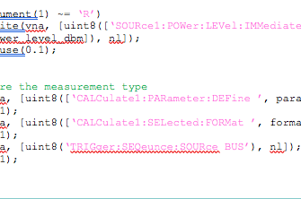
Usually, Copper Mountain Technologies instruments are locally automated on the same Windows-based PC to which the instrument is connected and the VNA control software is installed. Such functionality is readily achieved on a Windows-based PC by using the Component Object Model (COM), or ActiveX interface for automation. All that is required for automation of the instrument is the applicable VNA control software and its respective Programming Manual. The last page of the VNA control software installation wizard presents the option to register a COM interface server. If this box is checked and a confirmation dialogue pops up to confirm the registration, users are ready to begin programming.
Automation Interfaces of Copper Mountain Technologies’ Network Analyzers
August 3, 2018
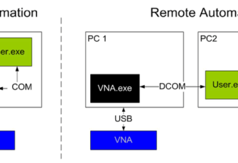
Copper Mountain Technologies’ VNAs can be readily automated and there are numerous options for users who wish to do so. To help illustrate the different automation methods and interfaces available, consider the components in an automated VNA measurement system. There is hardware: the VNA itself and a computer. There is software, as well: the VNA control software loaded onto the computer. While non-automated use of these components consists of each of these components in this basic configuration, automation options alter this configuration.

Copper Mountain Technologies’ Planar 808/1 Vector Network Analyzer Field-Tested at the Hamburg University of Applied Science
July 9, 2018
The Hamburg University of Applied Sciences is one of the larger technical universities in Germany. Over 1000 students study in the field of Electrical and Information Technology. In the Laboratory for Communication Technology, under the guidance of Prof. Ralf Wendel, training in the field of RF and Microwave Technology takes place. Students from the Electrical and Information Technology bachelor’s curriculum as well as the master’s program, Information and Communication Technology, participate in application of learned principles.
Voltage and Current Measurements with a VNA and DMM
April 20, 2018
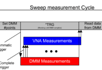
Vector Network Analyzers (VNAs) are used to measure the reflection and transmission coefficients, or S-parameters, of a Device Under Test (DUT). When the DUT is passive, the VNA may be the only tool necessary. But some devices are active and require an external power source for operation. In such active applications, it may be useful to perform voltage or current measurements of the DUT as the VNA generator sweeps over frequency or power.
Spectral Analysis with a Vector Network Analyzer
April 20, 2018
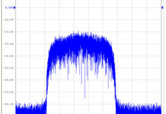
Vector network analyzers (VNAs) are widely used in research, manufacturing, and service environments. These instruments contain stimulus signal sources and receivers with one or more frequency converters. Copper Mountain Technologies produces several VNA models including the Planar 304/1 VNA with a frequency range of 100 kHz to 3.2 GHz and Planar 804/1 VNA with a frequency range of 100 kHz to 8.0 GHz.
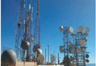
Wireless Infrastructure Maintenance with a USB-driven VNA
April 20, 2018
Wireless infrastructure encompasses a broad range of radio technologies, antennas, towers, and frequencies. Radio networks are built from this infrastructure and from mobile radios—the radios used by municipal and commercial customers to communicate over licensed frequency bands. Typical end user applications of such systems include local and regional law enforcement, highway and local maintenance dispatch, ambulance and fi re service dispatch, and federal law enforcement communications. Wireless infrastructure is often remotely located and difficult to access—or may be completely inaccessible—due to adverse weather conditions. It is critical to perform regular maintenance like visual inspection and RF testing of exterior cabling and antennas, and testing and adjustment of radios and combining networks. Maintenance is performed on two types of links: the RF radio networks and the microwave links that provide backhaul.
Optimizing VNA Measurement Speed
April 19, 2018
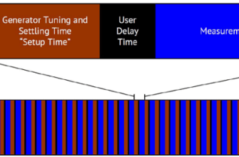
Users of Vector Network Analyzers (VNAs) often need to estimate and strive to optimize their instrument’s measurement speed. Many RF Engineers are interested in the tradeoffs between speed, accuracy and resolution in VNA measurements, especially those striving to achieve optimal automation of the instrument integrated in a larger measurement system or production environment. This application note details the determining factors for measurement cycle time in Copper Mountain Technologies VNAs. Generally speaking, the measurement cycle for any VNA consists of three major components: the per-point tuning and settling time of the generator, the per point measurement time, and a per-sweep time needed to process and transfer results, switch the generator between output ports, and return the generator to the start frequency. An additional, user-programmable delay between points is available in CMT instruments, which may be useful for integration with external equipment or DUTs with settling times of their own. As will be seen, some of the delay components are effectively fixed, while others depend upon the measurement parameters and thus may be optimized by the user.
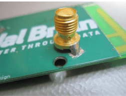
Wi-Fi, Bluetooth & PCB Tuning and Antenna Testing
April 19, 2018
RF Mixer Characterization
April 19, 2018
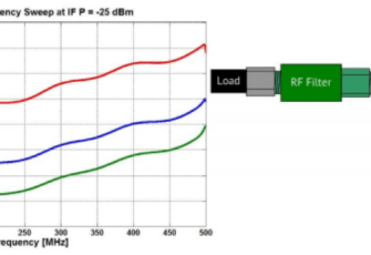
Mixers are 3-port devices that incorporate nonlinear elements, typically diodes or transistors, to produce the sum or difference of two input frequencies. For example, in transceivers mixers are used to translate radio frequencies (RF) to intermediate frequencies (IF) to allow easier, cheaper, and more accurate processing as well as to translate intermediate frequencies to RF for communication, especially over antennas which are more efficient and smaller at higher frequencies. Engineers developing mixers or integrating mixers in systems often need to measure mixer performance, including conversion loss, phase and group delay, the 1 dB compression point, isolation between ports, and port VSWR. Measurements characterizing these parameters are easily performed on Vector Network Analyzers (VNAs) with advanced calibration techniques, including Scalar Mixer Calibration (SMC) and Vector Mixer Calibration (VMC). Both of these calibration methods are described in detail in the operating manuals of Copper Mountain Technologies’ S2 family of VNAs, available for download at www.coppermountaintech.com. This application note will give a brief overview of mixer fundamentals, describe important mixer characteristics, and detail various measurement processes.
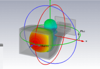
Design & Test a 3D Printed Horn Antenna
April 19, 2018
The horn antenna is an antenna that consists of a flaring metal waveguide shaped like a horn to direct radio waves into a beam. 3D printing is a fast-growing technology for rapid prototyping of mechanical structures at a relatively low cost. This enables quick production and demonstrations of experimental models and measurement results for innovative ideas. In this application note, we describe our experiences fabricating a pyramidal horn antenna using 3D printing technology.
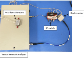
Multiport Testing with CMT VNAs & Off-the-shelf RF Switches
April 19, 2018
Copper Mountain Technologies offers VNA with one port, two ports or four ports. But sometimes, more ports are required, for example for testing multi-port devices. There are many options to achieve multi-port measurements, such as manually connecting and disconnecting each port, or using an OEM switch matrix system. Manual re-connection can be time-consuming to the point of being impractical, depending on the test requirements; on the other hand, test equipment vendors’ switch systems are relatively expensive especially considering these are often repackaged versions of commercially available switches.
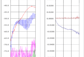
Measurements in 75 Ohm Coaxial Transmission Lines Using a 50 Ohm VNA
April 19, 2018
One application of a vector network analyzer (VNA) is the measurement of 75 Ω coaxial transmission lines. In this article, we will discuss making these measurements using the most common type of VNAs, which have 50 Ω test ports, in conjunction with 50Ω‐to‐75Ω Minimum Loss Pads (MLP), i.e. impedance‐matching attenuators with insertion loss of 5.7 dB. As 50Ω VNAs we suggest using the VNAs manufactured by Copper Mountain Technologies: PLANAR TR1300/1, PLANAR 304/1, and PLANAR 804/1 (as of 2012). The use of an MLP affects accuracy of measurements by changing the calibration error and, depending on the location of the attenuator in the measurement circuit, impacts stability of measurements related to test cable bending.
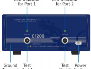
Using a VNA as a Signal Generator
April 19, 2018
A common question from users of Copper Mountain Technologies’ USB-based Vector Network Analyzers is whether the analyzer can be used as a signal source. Users’ motivations for doing so vary, but most commonly the question arises when an additional source is needed in a test setup but is not available. For example, a source might be needed as the LO to a mixer, to check functionality of another test equipment like a power meter or spectrum analyzer, or to produce a reference clock for use elsewhere in a test system. Fortunately, any CMT VNA can readily be used as a signal source. This application note describes the process of configuring a CMT VNA as a signal source, and the expected performance of an analyzer so-configured. This application note is based on the S2 family of instruments’ software; other instruments will follow similar menu structures and procedures.
Using Compact USB VNAs with an Off-the-shelf Battery
April 19, 2018
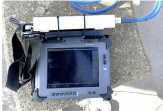
Copper Mountain Technologies provides Vector Network Analyzers without a built-in computer, which enables the VNAs to be highly compact, lightweight and very low power. Those characteristics allow for easily taking CMT’s well-known lab-grade measurement results into the field. There are three main categories of VNA form factor available from Copper Mountain Technologies: small, pocket-size devices (1-Port Cable and Antenna Analyzers); portable 2- port (Compact and M series devices); and rack mountable (Planar and Cobalt series 2- and 4-port instruments). Using the 1-Port and Compact VNAs when A/C mains are not available is very simple, though the latter requires using an external battery pack instead of the ordinary +12V supply. This application note describes both configurations, presents some recommendations, and shows photos taken in the field.
Using a Pair of Copper Mountain Technologies Vector Reflectometers
April 19, 2018
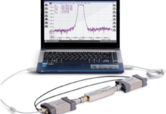
Reflectometers are used to measure the reflection, or S11 parameter, of a Device Under Test (DUT). This measurement only provides characterization of a single-ended device. For analysis of a twoport device, a traditional Vector Network Analyzer (VNA) is typically used. Using Copper Mountain Technologies’ R series reflectometers however, it is possible to configure two of these devices to measure all four S-parameters’ magnitudes for full characterization of a two-port device’s attenuation behavior.
Testing & Matching PCB Antennas
April 19, 2018
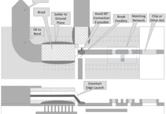
Connecting to an Antenna Under Test (AUT) integral to a Device (DUT) may involve some tradeoffs between measurement accuracy, electrical considerations, and mechanical ruggedness. In this paper, we describe some aspects of this connection with practical advice for such test and measurement scenarios.
Power Integrity Measurements with CMT VNAs and Picotest Accessories
April 19, 2018
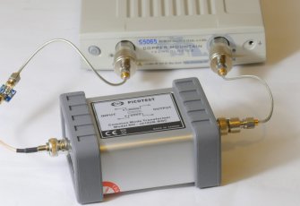
Power integrity measurements are essential in all modern electronics, including RF and Microwave circuits. Poor power integrity results in spurs and degraded phase noise. As is the case with RF and high speed signals the goal is a flat, frequency independent impedance. Unlike RF and high speed signals, the magnitude of the impedance is not defined, and must be determined based on the circuit noise tolerance. The power distribution network (PDN) measurement includes the voltage regulator, printed circuit board planes and decoupling capacitors. Measuring capacitors, ferrite beads and the PDN impedance can be a challenge, including very low impedance magnitudes large dynamic range and a wide frequency range. For example, the impedance of a 10 nF capacitor at 20 kHz is approximately 800 Ω while at its series resonant frequency it is on the order of 10 mΩ. Similarly, a ferrite bead might be 10 mΩ at 20 kHz and more than 500 Ω at resonance occurring as high as 100 MHz or more.
Calibration Types and Considerations
April 19, 2018
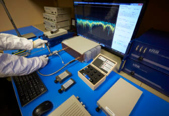
One of the most frequently asked questions we receive at Copper Mountain Technologies’ sales and support departments goes something like this: “What about calibration?” It’s an unfortunate reality that in the English language, Calibration has two completely distinct definitions. The first relates to checking out the instrument periodically to make sure it is operating within its specifications. “Performance test” is the procedure by which the analyzer performance is verified, typically annually. The second meaning is to do with Measurement or User calibration, a collection of techniques by which measurement accuracy is maximized and made to exclude elements of the system from those measurements (such as cables, adapters and the like). In this application note, we discuss both meanings of calibration as related to Copper Mountain Technologies’ Vector Network Analyzers (VNAs). First, we describe Annual Calibration and then later we discuss measurement calibration.
Conducting Calibration with the SOLR (Unknown Thru) Method
April 19, 2018
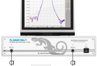
This article describes advantages of vector network analyzer (VNA) calibration by Unknown Thru (SOLR) method, compared to traditional SOLT calibration for measurement of 2-port noninsertable devices. Errors, which surface during SOLT calibration, are demonstrated. Recommendations are given for assessing the quality of the conducted SOLR calibration.
Automated Antenna Testing
April 19, 2018
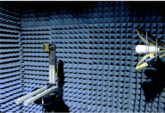
As the number of devices featuring wireless connectivity grows, ensuring their performance specifications while staying within regulatory requirements becomes even more important. Antenna pattern measurement is a critical step in the design process of antennas and wireless devices. Compact antenna measurement systems combined with a high performance VNA are necessary to characterize parameters such as pattern, gain, VSWR, and efficiency. These results are used to validate simulated designs and identify possible performance issues before final testing. By using an in-house measurement system, multiple design revisions can be tested and pre-certified without the high cost of using an accredited or certified measurement facility for each test. Other considerations like portability and low cost are important to engineers in various environments like defense or education, respectively.
Using a Databased SOLT Calibration Kit
April 19, 2018
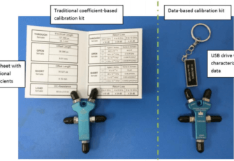
Copper Mountain Technologies produces lab-grade VNAs with outstanding measurement accuracy. As with every VNA, performing a good calibration is necessary for maximizing the accuracy of VNA measurement results, for de-embedding the effects of imperfect cables and components in the fixture, and for moving the reference plane to the DUT interfaces. There are several approaches for determination and application of VNA measurement corrections, including port extension (a relatively crude, approximate method), fixture de-embedding (with accuracy depending on correctness of the model), and calibrating with a calibration kit (a high accuracy approach). Generally, there are two broad categories of calibration kit types: traditional mechanical kits and automatic/electronic calibration modules. Within mechanical kits, there are two types of kits: those with standard “polynomial” coefficients and those with full S-parameter characterization data, also known as databased kits. This application note introduces databased calibration kits, explains why their use is growing in popularity, and describes how they can be used with Copper Mountain Technologies VNAs.
Waveguide Calibration of Copper Mountain Technologies’ VNAs
April 19, 2018
Waveguide components possess certain advantages over their counterpart devices with co-axial connectors: they can handle larger power and exhibit lower loss. Therefore, it is very common to employ waveguide interfaces in the high power devices, such as microwave transmitters. The performance of waveguide components at microwave frequencies are typically measured with a Vector Network Analyzer (VNA). However, when measuring the performance of waveguide components with a VNA, non-idealities of any uncalibrated VNA introduce uncertainty in the measurement results. This application note describes how to perform an SSL calibration with a Copper Mountain Technology VNA. It also covers the procedures and the calculations to define a waveguide calibration kit in the CMT VNA. Finally, it provides an example of the 1-port return loss measurement of a waveguide band-pass filter.
Passive RF System Measurements in a Strong RF Environment: Using an Amplifier with a 2-Port VNA
April 19, 2018
It is sometimes necessary to evaluate passive RF systems in environments where there is significant ingress from other sources. The most common cases are antenna system measurements at community transmitter sites. If there is sufficient RF present in the near field, the antenna being tested doesn’t even need to be particularly broadband for problems to arise. Vector network analyzers are sensitive instruments, typically operated at very low signal levels. Ingress from local sources can skew measurements, and if the ingress is strong enough the analyzer can be damaged. Coordinating multiple station sign-offs can be difficult, if not impossible. When working with broadband antennas in a large market, the interferer doesn’t even need to be collocated to impact the measurements. With another repacking of broadcast spectrum looming, the congestion will only get worse.
DCOM Configuration Guide
April 18, 2018
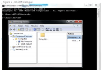
Usually, automation of Copper Mountain Technologies instruments is achieved on the same computer which is running the VNA applications. Such functionality can be readily achieved using COM, or ActiveX automation. Nothing is required for automation of the instrument other than the PlanarR54.exe application and its Programming Manual. When you install the application, on the last page of the wizard there's an option to register the COM server. If this box is checked and you see a confirmation dialogue pop up, you are ready to begin programming.

Automation via Wireless (or Ethernet) USB Sharing Hubs
April 18, 2018
There are several ways to control Copper Mountain Technologies’ VNAs. In the simplest and most typical configuration, users directly control the VNA or write automation programs that execute on the same PC which is running the CMT VNA software application. The PC must be located within a USB cable’s reach of the VNA, or within several cables’ reach if daisy chained together. There are several other approaches to control CMT VNAs remotely; pros and cons of these are found in the table at the end of this note.
Antenna Statistics of Handheld Wireless Devices with a 1-Port R54
April 17, 2018
A cell phone’s GSM antenna is typically located on the lower back side of the phone so as to keep the radiating elements as far from the user’s hand and body as practical. With the small size of today’s phones, that is not necessarily very far, but it at least minimizes the Specific Absorption Rate (SAR) of transmit power and maximizes the receive sensitivity if the carrier has a Total Isotropic Sensitivity (TIS) requirement. Clever industrial design can encourage the user to hold the phone so that the hand doesn’t cover the antenna, but the user presents a challenge anyway in how the phone is actually held during conversation.
Getting Started with the CMT VNA: Top 10 Tips and Tricks
February 14, 2018
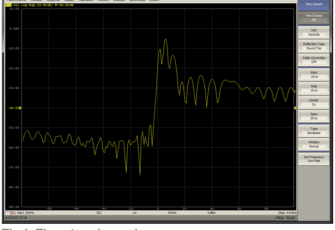
The examples created in this document are based on the S5048, but apply to most of the Copper Mountain Technologies VNAs in a similar way. These tips will help you use your VNA with ease and help you get more intuitive results.

Why USB VNAs?
February 14, 2018
USB VNAs separate the measurement module from the processing module, bringing the measurement results to any external PC using the VNA software. The user can take advantage of the latest OS processing power, bigger display, and more reliable performance of an external PC while simplifying maintenance of the analyzer. USB VNAs are flexible. They can be easily adapted to multiple users and are well-suited for lab, production, field, and secure testing environments.

What Makes a Good VNA?
February 14, 2018
Everyone knows that a good VNA should have both excellent hardware performance and an easy to use software interface with useful post-processing capabilities. There are numerous VNAs in the market with different performance levels; some of them are economy grade, and others are truly laboratory test grade. What separates the two?

Product Leader for USB VNAs
February 14, 2018
Frost & Sullivan awarded the 2017 Global Product Leadership Award for USB VNAs to CMT, because we are at the forefront of this trend for affordable and portable high-quality VNAs.
Measurement of High Power Devices
February 14, 2018
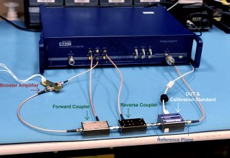
High input power requirements of some Devices Under Test (DUTs) introduce challenges to the measurement therefore. Various measurement techniques such as load-pull analysis and noise figure measurement may also require a higher input power to the DUT than the maximum output power of the VNA.
A Guide to CMT VNA Software Families and VNA Series
February 14, 2018
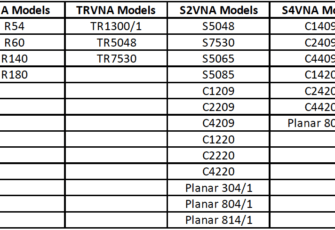
Copper Mountain Technologies (CMT) provides a variety of Vector Network Analyzers (VNA) to accommodate a wide range of test and measurement needs. The CMT VNA family covers a wide span of frequencies starting from 20 kHz, and extending to 20 GHz, with 1-port, 2-port or 4-port configurations. 2-port VNAs are further divided into two groups: one capable of measuring 2-port 1-path measurements, and the other capable of full 2-port 2-path measurements.

Copper Mountain Technologies Planar 304/1 Network Analyzer Initial Testing Report
March 7, 2013
This test report analyzes the Copper Mountain Technologies Planar 304/1 Network Analyzer. The analyzer has a frequency range of 0.3 MHz – 3.2 GHz. Much of this report compares test results from the Copper Mountain network analyzer to an Agilent E8364B PNA Network Analyzer that has a frequency range of 10 MHz – 50 GHz. The Agilent analyzer was calibrated in the fall of 2012 and has brand new cables that interface devices to the test ports. It is expected that the Agilent analyzer gives very accurate results and can be trusted as a reliable benchmark. It should be noted that all tests performed here were done so in an informal nature. Both analyzers were not located in the same exact location and the same cables were not used at all times. Small differences that appear in the data may be attributed to these testing differences. Any calculations or presentation of data was also done to look at estimated results. All of the testing was aimed at getting good solid estimates not high quality measurements accurate to a tenth of a dB. More rigorous analysis can be performed in the future if desired. However, for now these initial experiments gave satisfactory results.

